
SAM is a medium size small-angle neutron scattering (SANS) instrument, developed by the Laboratoire Léon Brillouin (LLB) in collaboration with the ‘Institut Laue Langevin (ILL, Grenoble). Its construction was proposed in the frame of the ILL “Endurance II” rejuvenation programme, with two main objectives in mind:
(i) Maintain an access to SANS beam time for the French community beyond the shutdown of the Orphée reactor,
(ii) Develop a versatile instrument expanding the capabilities of the SANS technique, namely towards high-resolution spectroscopy.
To these ends, SAM will consist in a conventional “pin-hole” SANS instrument working with either an unpolarised or a polarised neutron beam. Thanks to its position at one end of the fully renovated H15 guide, the incoming flux at the sample position shall be very similar to that of the world-leading D22 and D33 instruments already running at the ILL. SAM will also be equipped with a so-called “MIEZE” option enabling high-resolution spectroscopy with sub-μeV resolution, irrespective of the sample or its environment. The commissioning of SAM will take place in June 2024. It will be then operated as a “CRG” instrument, with an even split of the beam time between the ILL user program and the French community [1].
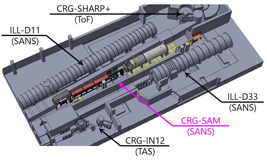
Fig. 1 – Layout of the SAM instrument in the ILL7 guide hall (Vercors side).
Project team

Annie Brûlet (project coordinator)
Marc Detrez, Christophe Meunier (mechanics)
Patrick Lambert, Emmanuel Rampnoux (electronics)
Pascal Lavie (lead engineer)
Nicolas Martin (lead scientist)
Maycki Thiébault, Anne-Laure Remot (CAD)

Lester Clarke, Luc Didier (CAD)
(with support from the H15 project team
and technical services)
Science drivers
SANS is a ubiquitous neutron scattering technique, devoted to the study of “mesoscopic” structures involved in scientific cases spanning soft- and hard-condensed matter, biophysics and material science. The simultaneous knowledge of the spatial configurations and of dynamical properties of the studied structures is often required to understand, and further tune, the materials’ functionalities. SAM will allow studying this interplay over a large parameter range (≈ 0.1 – 100 nm in space and ≈ 0.1 ps – 10 ns in time) and under a large set of environments (low temperatures, high fields and pressures, stop-flow cells, etc.).
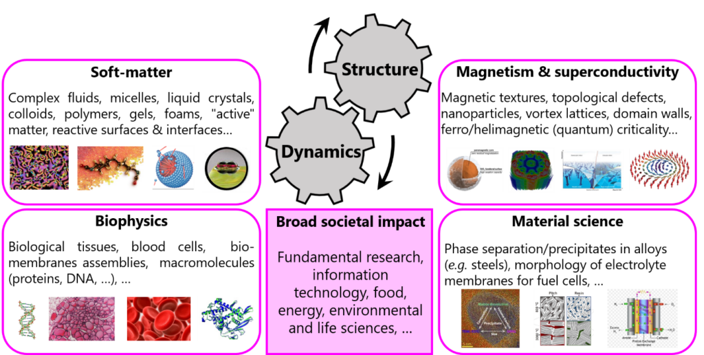
Fig. 2 –Overview of the scientific areas covered by SAM.
Detailed description
Guide system – SAM will be located at the end of the dedicated H151b branch (32 m curved section followed by a 4 m straight section) of the renewed H15 guide. Its cross section is 40 x 30 (H x V) mm with m = 1 coating (except on the exterior side of the curve where m = 1.6). The larger horizontal dimension and the increased m value on the exterior side limit losses at the shortest wavelengths, due to the guide curvature and the selector gap. The guide cross section is then reduced to 30 x 30 mm throughout the instrument.
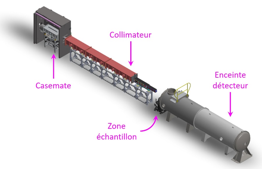
Fig. 3 – 3D model of SAM.
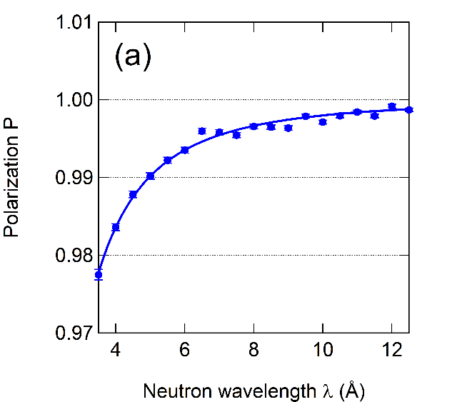
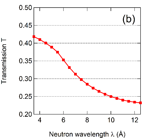
Casemate – The first part of the instrument is the so-called casemate, hosting the elements allowing to monochromatize and polarize the incoming beam. Neutron wavelength will be set using a conventional helical velocity selector (3.5 ≤ λ ≤ 20 Å, Δλ/λ = 10 %) and the monochromatic beam intensity shall be monitored using a thin 235U fission chamber (efficiency ≈ 10-6). Downstream, an evacuated chamber will host an automatized changer allowing to insert either a 1.37 m polarising double V-cavity (FeSi blades, m = 4) or a non-polarising guide element (m = 1) in the beam. In order to reduce the number of windows, this chamber is connected to the collimator by non-magnetic hoses, thereby forming a common evacuated volume. These hoses also serve as a support for a RF spin flipper, allowing to select the beam polarization state without interposing material in the beam. All the above elements will rest in a steel casemate dimensioned to comply with the radioprotection regulation applicable at the ILL.

Fig. 4 – (a) Casemate of the SAM instrument. (b) Polarizer/guide translation table. (c) RF spin flipper and subsequent guide field. Both are installed around the vacuum hoses connecting the polarizer and collimator vessels.
Collimator – SAM’s casemate is followed by a 9 m long collimator, resting on a “monoblock” frame through mechanical decoupling pads. This system ensures that the neutron guides alignment will be unaffected by slight modifications of the vessel’s geometry upon inner pressure changes. The collimator contains a linear attenuator changer (sintered 10B4C + Gd sieves with varying hole density) and a series of 3 continuously adjustable diaphragms. The latter are each equipped with 4 independent sintered 10B4C blades, allowing to continuously tune the beam shape/size. These diaphragms are separated by 2 x 2 m and 2.5 m non polarising guide elements (m = 1). All the above elements are designed so has to be as amagnetic as possible, since the collimator will be immersed in a homogeneous magnetic guide field (≈ 15 Oe) produced by magnetized rubber bands. At the end of the collimator tank, a retractable nose (length = 1 +/- 0.5 m) will allow tuning the effective collimation length as well as the space needed to accommodate any kind of sample environments.
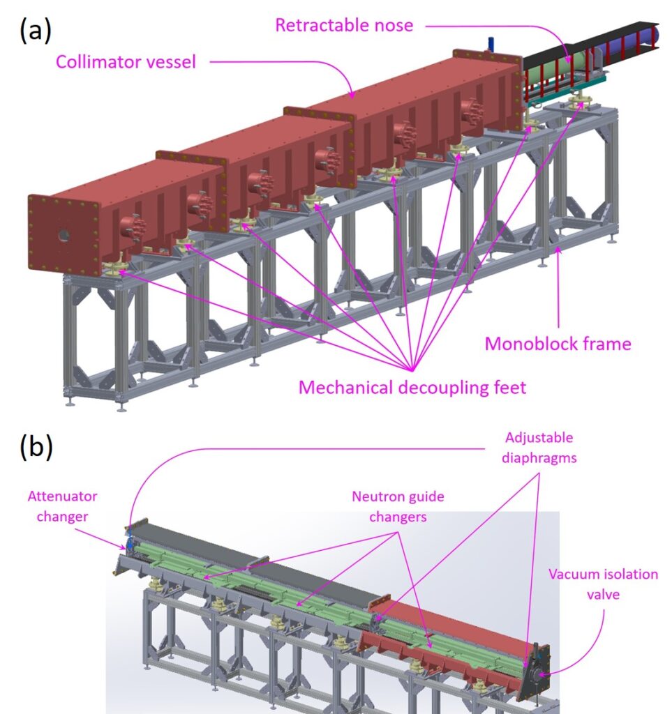
Fig. 5 – Collimator of the SAM instrument.
Sample environment – SAM will be equipped with a sample table able to carry bulky environments (with weights up to 800 kg). This table is endowed with 6 independent motions, namely translations and rotations along/around the 3 directions. Ancillary equipment includes a 24 positions thermostated sample changer and a 10 T horizontal field cryomagnet.
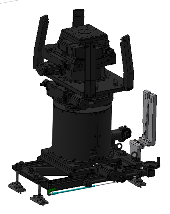
Fig. 6 – View of the sample table. A custom pivot system (shown in gray) will allow rotating the detector vessel w.r.t. its center of rotation.
Detector vessel – In order to perform SANS experiments, SAM will be equipped with a position-sensitive 3He detector (ILL MAM128) with a 64 x 64 cm² area (128 x 128 pixels). This detector will be placed in the renovated detector vessel of the former PAXY instrument (LLB). Its dimensions allows for sample-to-detector distances between ≈ 1 and 7 m. The vessel itself will be attached to the sample table and it will be possible to rotate it w.r.t. the incoming beam axis to increase the accessible Q-range.
“MIEZE” option – MIEZE is a derivative of neutron spin echo (NSE) spectroscopy [3]. It employs a pair of RF spin flippers (RFSF) to produce a time-modulation of the beam polarization upstream of the sample. By inserting a spin analyser between the second RFSF and the sample, the polarization modulation is converted into an intensity modulation at frequencies as high as a few MHz. This method allows probing slow nuclear or magnetic dynamics with high resolution (sub-μeV) or to perform stroboscopic experiments over μs-s time scales. As compared with NSE, MIEZE is insensitive to any source of depolarization due to the sample or its environment [4]. This clearly offers novel opportunities in high-resolution spectroscopy, especially in the field of magnetism [5]. MIEZE works optimally in the SANS regime which makes it a very interesting option for the SAM instrument [6]. In order to record the modulated signal, a second detector (10 x 10 cm “SoNDe” tile [7]) will be placed in the evacuated vessel and it will be possible to move it in the plane transverse to the neutron beam to reach the desired Q-position.
Expected performances
Neutron flux – Ray-tracing simulations (McStas framework) of the complete guide system (i.e., from the vertical cold source to the sample position) have been used to optimize the parameters of the curved H151b branch (bent to the right over 32 m with a radius of 1500 m). The optimal geometry was found to be a rectangular cross section (H 40 x V 30 mm) with a m = 1 coating on the top, bottom and right sides and m = 1.6 on the left side. These simulations suggest that SAM will display performances comparable to the world-class SANS instruments D22 and D33 in terms of flux at the sample position.


Fig. 7 – (a) McStas simulation of the wavelength-dependent monochromatic flux incident on the sample as a function of the effective angular resolution Δθ = D1/2L1, where D1 is the source size and L1 the collimation length. (b) Monochromatic flux incident on the sample at λ = 6 Å obtained from McStas simulations (SAM) and measurements (D22 and D33, from [2]). The thick pink line represents a scaling down of the simulated flux by 40 %, to account for imperfect guide surfaces and alignments.
Références
[1] Access provided through the French Federation for Neutron Scattering (2FDN)
[2] C. Dewhurst et al., J. Appl. Cryst. 49, 125110 (2016)
[3] R. Gähler et al., Neutron resonance spin echo-a new tool for high resolution spectroscopy, Physica B 180 & 181 (1992) 899-902
[4] J. Kindervater et al., EPJ Web of Conferences 83 (2015) 03008
[5] C. Franz et al., J. Phys. Soc. Japan 88, 081002 (2019)
[6] N. Martin, Nucl. Inst. Meth. In Phys. Res. A 882 (2018) 11-16


